Controlling electrical devices with your smartphone has never been easier, thanks to Wi-Fi-enabled microcontrollers like the NodeMCU. In this DIY project, you’ll learn how to build a Wi-Fi Controlled Relay that lets you switch any appliance on/off from your phone — without any remote or switch.
This beginner-friendly project is perfect for smart home enthusiasts, students, and DIYers. Let’s dive into the full guide!
📌 Table of Contents
Contents
- 1 📌 Table of Contents
- 2 🔍 What is a Wi-Fi Controlled Relay?
- 3 ✨ Features
- 4 💡 Applications
- 5 ✅ Required Components
- 6 🧠 How It Works
- 7 📊 Circuit Diagram
- 8 🛠️ How to Make a Wi-Fi Controlled Relay – Step-by-Step
- 9 🧾 Arduino Code for Wi-Fi Relay
- 10 🔍 How to Use
- 11 ❓ FAQs – Wi-Fi Controlled Relay
- 12 🧠 Final Thoughts
- What is a Wi-Fi Controlled Relay?
- Features
- Applications
- Required Components
- Circuit Diagram
- How It Works
- How to Make It (Step-by-Step Guide)
- Arduino Code
- FAQs
- Final Thoughts
🔍 What is a Wi-Fi Controlled Relay?
A Wi-Fi Controlled Relay is an IoT-based switch that connects to your home Wi-Fi network and allows you to control appliances using a smartphone or browser. It uses a Wi-Fi microcontroller (like NodeMCU/ESP8266) and a relay module to switch high-voltage loads safely.
✨ Features
- 📱 Control using your smartphone via browser
- 🌐 Wi-Fi connectivity using NodeMCU (ESP8266)
- 🔌 Can switch AC devices (like fan, light, charger)
- 🛡️ Fully isolated relay control
- 🧠 Easy to modify and expand (add more relays or sensors)
- 🔧 DIY-friendly and low cost
💡 Applications
- Smart home automation
- Remote-controlled light or fan
- Automatic plant watering system
- Wireless switch for power outlets
- Voice control (via Google Assistant + IFTTT integration)
✅ Required Components
| Component | Quantity | Notes |
|---|---|---|
| NodeMCU (ESP8266) | 1 | Microcontroller with built-in Wi-Fi |
| 5V Relay Module (1-Channel) | 1 | Opto-isolated preferred for AC safety |
| AC Appliance (e.g., Bulb, Fan) | 1 | Use with caution, must be plugged through a relay |
| Female Plug + Socket | 1 | For AC appliance connection (optional but recommended) |
| Jumper Wires (Male-to-Female) | 5+ | For relay-to-NodeMCU connections |
| Breadboard or PCB | 1 | Optional, but helps keep circuit stable |
| Micro USB Cable | 1 | For programming and powering NodeMCU |
| USB Charger or 5V Adapter | 1 | To power NodeMCU after uploading the code |
| Screwdriver + Wire Cutter | 1 set | For wiring relay to AC terminals |
| 2-pin Wire or Power Cord | 1 | For relay COM/NO connection to appliance |
🔐 Safety Tip:
If you’re working with AC 220V, always use a plug board for testing. Never handle live wires directly — use a proper relay module with screw terminals and opto-isolation.
⚠️ Safety Note: Relays handle AC voltage. Take proper precautions or use an AC bulb connected through a plug board during testing.
🧠 How It Works
The NodeMCU connects to your Wi-Fi and hosts a simple web server. When you access the NodeMCU IP in a browser, you’ll see ON/OFF buttons. Clicking these buttons sends signals to the relay module which, in turn, turns the connected appliance ON or OFF.
📊 Circuit Diagram
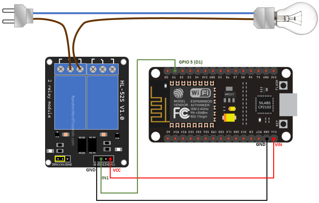
Here’s the correct circuit diagram showing how to connect the NodeMCU to a 5V Relay Module:
1. NodeMCU ↔ Relay Module (3 Wires)
These are low-voltage connections:
| From NodeMCU | To Relay Module | Purpose |
|---|---|---|
| D1 (GPIO5) | IN | Control signal to turn relay ON/OFF |
| G (GND) | GND | Common ground |
| VIN | VCC | Powers relay module (5V input) |
📌 You can also use 3.3V from NodeMCU in some relay modules, but 5V (VIN) is safer and more reliable.
2. Relay Module ↔ AC Appliance (3 Wires)
These are high-voltage (230V) wires, handled carefully:
| Relay Terminal | Connected To | Description |
|---|---|---|
| COM | Live wire (from AC plug) | Entry point for power |
| NO (Normally Open) | Live input of appliance | Only connected when relay is ON |
| Neutral | Direct to appliance | Goes from wall socket to appliance |
⚠️ Make sure to insulate all AC connections properly or use a plug-and-socket setup.
🛠️ How to Make a Wi-Fi Controlled Relay – Step-by-Step
🔌 Step 1: Hardware Setup
- Connect IN of Relay Module to D1 (GPIO5) on NodeMCU.
- Relay VCC → NodeMCU 3V, GND → GND.
- Plug in your relay’s NO/NC and COM terminals as per device.
- Optional: Add a plug socket and connect the appliance through it for safe testing.
🔁 Step 2: Upload Arduino Code
- Install ESP8266 board from Arduino IDE board manager.
- Connect NodeMCU via USB.
- Upload the following code.
🧾 Arduino Code for Wi-Fi Relay
cppCopyEdit#include <ESP8266WiFi.h>

// Replace with your network credentials
const char* ssid = "Your_SSID";
const char* password = "Your_PASSWORD";

WiFiServer server(80);

const int relayPin = D1;

void setup() {
  Serial.begin(115200);
  pinMode(relayPin, OUTPUT);
  digitalWrite(relayPin, HIGH); // Relay OFF initially

  WiFi.begin(ssid, password);
  while (WiFi.status() != WL_CONNECTED) {
    delay(500);
    Serial.print(".");
  }

  Serial.println("");
  Serial.print("Connected to ");
  Serial.println(ssid);
  Serial.print("IP address: ");
  Serial.println(WiFi.localIP());

  server.begin();
}

void loop() {
  WiFiClient client = server.available();
  if (!client) return;

  while(!client.available()) delay(1);

  String request = client.readStringUntil('\r');
  client.flush();

  if (request.indexOf("/ON") != -1) {
    digitalWrite(relayPin, LOW); // Relay ON
  }
  if (request.indexOf("/OFF") != -1) {
    digitalWrite(relayPin, HIGH); // Relay OFF
  }

  // HTML Response
  client.println("HTTP/1.1 200 OK");
  client.println("Content-Type: text/html");
  client.println("");
  client.println("<!DOCTYPE HTML>");
  client.println("<html>");
  client.println("<h1>Wi-Fi Relay Control</h1>");
  client.println("<a href=\"/ON\"><button>ON</button></a>");
  client.println("<a href=\"/OFF\"><button>OFF</button></a>");
  client.println("</html>");
}
🔐 Note: Replace
"Your_SSID"and"Your_PASSWORD"with your Wi-Fi credentials.
🔍 How to Use
- Power NodeMCU via USB or 5V.
- Open Serial Monitor at 115200 baud. Note the IP address.
- Type that IP in your phone or PC browser (on the same Wi-Fi).
- Tap ON/OFF — your relay should click, and your device will respond.
❓ FAQs – Wi-Fi Controlled Relay
Q1. Can I control multiple relays with this code?
Yes! Just add more relays to unused GPIOs and duplicate the HTML & code logic.
Q2. Is it safe to control 230V appliances?
Yes, as long as your relay module is properly rated and isolated. Avoid touching any AC lines.
Q3. Can I control it from outside my home Wi-Fi?
Yes, using port forwarding or services like Blynk or Telegram Bot for remote control.
Q4. Can I use ESP32 instead of NodeMCU?
Absolutely! Just update pin numbers accordingly.
🧠 Final Thoughts
Building a Wi-Fi Controlled Relay is an excellent way to get started with home automation and IoT. It’s cost-effective, simple, and can be expanded into full smart home systems.
If you’re interested in turning this into a full Alexa or Google Assistant-controlled switch, stay tuned — we’ll cover that in upcoming posts!
💬 Need Help?
If you face any problems while making this project, feel free to ask your question in the comments below. I’d love to help you troubleshoot!