Build your own Line Following Robot using Arduino with this beginner-friendly tutorial. Includes circuit diagram, required components, working principle, and tested Arduino code.
🧠 How the Line Following Robot Works
Contents
- 1 🧠 How the Line Following Robot Works
- 2 🧰 Required Components for Line Following Robot
- 3 Circuit diagram + connections
- 4 🛠️ Step-by-Step Guide to Make a Line Following Robot
- 4.1 🔧 Step 1: Assemble the Chassis
- 4.2 🧲 Step 2: Mount the Components
- 4.3 🔌 Step 3: Connect the IR Sensors to Arduino
- 4.4 ⚙️ Step 4: Connect the Motors to L298N
- 4.5 ⚡ Step 5: Connect L298N to Arduino
- 4.6 🔋 Step 6: Power Up the Circuit
- 4.7 🧠 Step 7: Upload the Arduino Code
- 4.8 🧪 Step 8: Test on a Line Track
- 4.9 🔧 Troubleshooting Tips
- 5 📜 Arduino Code for Line Following Robot
- 6 🧪 Testing & Working of Line Following Robot
- 7 ❓ Frequently Asked Questions (FAQs)
- 8 📣 Need Help? Ask in the Comments!
A Line Following Robot is an autonomous robot that can detect and follow a specific path — usually a black line on a white surface. It’s one of the most popular beginner-level robotics projects because it introduces key concepts in sensors, motor control, and logic-based programming.
🔍 Core Working Principle
The robot uses IR (Infrared) sensors to detect the color contrast between the black line and the white background. Here’s how:
- Black surfaces absorb IR light, while white surfaces reflect it.
- The IR sensor module sends IR light to the ground and receives the reflected light.
- Based on the amount of reflected IR light, the sensor outputs either HIGH (white surface) or LOW (black line).
🤖 Behavior Logic
A typical robot uses two IR sensors (left and right). The logic works like this:
| Left Sensor | Right Sensor | Robot Action |
|---|---|---|
| White | White | Stop or idle |
| Black | White | Turn left |
| White | Black | Turn right |
| Black | Black | Move forward |
🔁 Continuous Monitoring
- The Arduino constantly reads the sensor data.
- Based on the input, it controls the direction of the motors via a motor driver (usually L298N or L293D).
- This results in real-time tracking of the black line.
🧠 Summary of Logic Flow
- IR Sensors detect the line.
- Arduino processes the signals.
- Motor driver moves the robot in the correct direction.
- The process repeats continuously, enabling smooth following of the path.
🧰 Required Components for Line Following Robot
Below is the list of all parts you’ll need to successfully build the project:
| Component | Quantity | Description |
|---|---|---|
| Arduino Uno / Nano | 1 | Acts as the brain of the robot |
| L298N Motor Driver Module | 1 | Controls motor direction and speed |
| IR Sensor Module | 2 | Detects the black line against a white surface |
| BO Motors (DC Gear Motors) | 2 | Drives the robot wheels |
| Wheels (compatible with BO motors) | 2 | Attached to BO motors |
| Caster Wheel | 1 | Provides support and balance at the front/back |
| Robot Chassis | 1 | Base frame to mount all components |
| Battery Pack (4x AA or 9V) | 1 | Powers the entire robot |
| Male-to-Female Jumper Wires | 15+ | For connecting sensors, motors, and modules |
| Double-sided tape / Screws / Bolts | As needed | For fixing components to the chassis |
| Breadboard (optional) | 1 | Can be used for easy connections (optional) |
🔋 Power Note:
- If using Arduino Uno, a 9V battery or 6V AA battery pack works.
- The motor driver gets powered directly from the battery, while the Arduino can be powered via VIN or separate power jack.
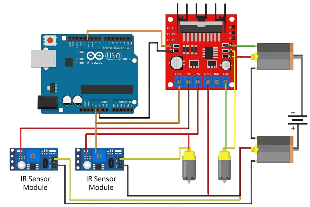
Circuit diagram + connections
🛠️ Step-by-Step Guide to Make a Line Following Robot
This guide walks you through the complete build — from hardware setup to wiring and testing. Perfect for beginners and DIY hobbyists.
🔧 Step 1: Assemble the Chassis
- Unbox your robot chassis kit or prepare a flat base (like acrylic or plastic).
- Mount the two BO motors on either side using screws or brackets.
- Attach wheels to the motor shafts securely.
- Fix the caster wheel at the opposite end for balance and support.
🧲 Step 2: Mount the Components
- Attach the L298N motor driver to the top or middle of the chassis.
- Mount the IR sensor modules at the front bottom side, facing down. Ensure they are close to the ground (~1 cm).
- Secure the Arduino Uno/Nano on top using double-sided tape or screws.
- Place the battery holder safely at the center or back of the robot to balance the weight.
🔌 Step 3: Connect the IR Sensors to Arduino
| IR Sensor Pin | Connects To |
|---|---|
| VCC | Arduino 5V |
| GND | Arduino GND |
| OUT (Left) | Arduino D2 |
| OUT (Right) | Arduino D3 |
✅ Make sure the IR sensors are aligned parallel to the ground and respond to black/white surfaces.
⚙️ Step 4: Connect the Motors to L298N
| Motor Driver Pin | Connects To |
|---|---|
| OUT1 & OUT2 | Left Motor |
| OUT3 & OUT4 | Right Motor |
⚡ Step 5: Connect L298N to Arduino
| L298N Pin | Arduino Pin | Function |
|---|---|---|
| IN1 | D4 | Left Motor Control 1 |
| IN2 | D5 | Left Motor Control 2 |
| IN3 | D6 | Right Motor Control 1 |
| IN4 | D7 | Right Motor Control 2 |
| ENA | 5V or D9 (PWM) | Enable Left Motor |
| ENB | 5V or D10 (PWM) | Enable Right Motor |
| GND | Arduino GND | Common ground |
You can connect ENA/ENB directly to 5V if you don’t need speed control.
🔋 Step 6: Power Up the Circuit
- Connect the battery pack to the L298N’s +12V and GND terminals.
- Ensure Arduino shares ground with L298N (very important).
- You can power Arduino separately using a 9V battery or via the VIN pin from L298N (if supported).
🧠 Step 7: Upload the Arduino Code
- Connect Arduino to your PC via USB.
- Open the Arduino IDE and paste the code (we’ll write it next).
- Select the correct board and port.
- Click Upload.
Once uploaded, disconnect USB and let the robot run on battery.
🧪 Step 8: Test on a Line Track
- Prepare a black line on a white surface (use black tape or marker).
- Place the robot at the start of the line.
- Turn on the power.
- The robot should detect the line and move forward, turning left or right to stay on the path.
🔧 Troubleshooting Tips
- If the robot moves off-track, reverse motor wires.
- Adjust the IR sensors if they don’t detect black/white properly.
- Check battery voltage — motors require decent power to move.
📜 Arduino Code for Line Following Robot
Upload this code to your Arduino Uno/Nano after completing the connections:
cppCopyEdit// IR sensor pins
const int leftSensor = 2;
const int rightSensor = 3;

// Motor control pins
const int in1 = 4;
const int in2 = 5;
const int in3 = 6;
const int in4 = 7;

void setup() {
  // Set IR sensor pins
  pinMode(leftSensor, INPUT);
  pinMode(rightSensor, INPUT);

  // Set motor pins as output
  pinMode(in1, OUTPUT);
  pinMode(in2, OUTPUT);
  pinMode(in3, OUTPUT);
  pinMode(in4, OUTPUT);
}

void loop() {
  int leftStatus = digitalRead(leftSensor);
  int rightStatus = digitalRead(rightSensor);

  if (leftStatus == LOW && rightStatus == LOW) {
    // Move forward
    forward();
  } else if (leftStatus == LOW && rightStatus == HIGH) {
    // Turn left
    left();
  } else if (leftStatus == HIGH && rightStatus == LOW) {
    // Turn right
    right();
  } else {
    // Stop
    stopMotors();
  }
}

void forward() {
  digitalWrite(in1, HIGH);
  digitalWrite(in2, LOW);
  digitalWrite(in3, HIGH);
  digitalWrite(in4, LOW);
}

void left() {
  digitalWrite(in1, LOW);
  digitalWrite(in2, HIGH);
  digitalWrite(in3, HIGH);
  digitalWrite(in4, LOW);
}

void right() {
  digitalWrite(in1, HIGH);
  digitalWrite(in2, LOW);
  digitalWrite(in3, LOW);
  digitalWrite(in4, HIGH);
}

void stopMotors() {
  digitalWrite(in1, LOW);
  digitalWrite(in2, LOW);
  digitalWrite(in3, LOW);
  digitalWrite(in4, LOW);
}
🧪 Testing & Working of Line Following Robot
Once everything is assembled and the code is uploaded:
- Create a path using black electrical tape or a bold black marker on a white surface.
- Place the robot at the start of the line and power it on.
- If everything is correct:
- The robot will detect the black line using IR sensors.
- Based on the line’s position, it will automatically steer left or right.
- When both sensors detect black, the robot will move forward.
- If both see white (off-track), the robot will stop.
🧪 Real-World Test Tips:
- Use a contrasting surface — black line on a white base works best.
- If the robot keeps moving off-track, try reversing motor polarity or tweaking sensor positions.
- Make sure the IR sensors are about 1 cm from the ground for accurate detection.
❓ Frequently Asked Questions (FAQs)
🔹 Can I use Arduino Nano instead of Uno?
Yes! Arduino Nano works perfectly and is even more compact — ideal for tight chassis spaces.
🔹 Why does my robot not follow the line?
Check the IR sensors. Ensure:
- Sensors are facing downward
- They are powered properly (5V)
- The output wires are going to the correct digital pins
🔹 Do I need to use PWM (speed control)?
PWM is optional. You can connect ENA and ENB to 5V directly. If you want speed control, use PWM pins and analogWrite() in code.
🔹 Can I use 6V motors with L298N?
Yes. The L298N supports motor voltages from 5V to 12V. Just ensure your battery pack delivers sufficient current.
🔹 How long does the battery last?
With AA batteries, expect 15–30 minutes of operation depending on motor efficiency and load.
📣 Need Help? Ask in the Comments!
Having trouble getting your Line Following Robot to work?
Drop your questions in the comments below, and I’ll personally help you debug your circuit, code, or setup. Whether you’re a beginner or hobbyist, I’m here to help you succeed!